Node

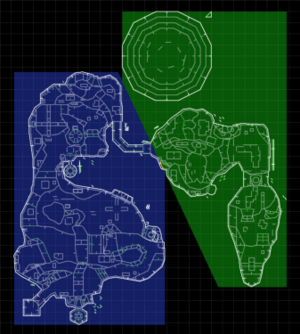
Nodes are data structures which constitute a binary space partition of a map. They are generated by nodebuilders, and they make up a binary tree that sorts all the subsectors into the correct order for drawing. Each node entry has a partition line associated with it that divides the area that the node represents into a left child area and a right child area. Each child may be either another node entry (a subnode), or a subsector on the map.
The node divisions for a map can be viewed in Zone Builder by going to the "Nodes Viewer" mode and switching to the "Splits" tab.
Specification
SRB2 supports vanilla Doom's node format, as well as extended and GL node formats.
Doom node format
The nodes for a map are stored in the NODES lump as a list, with the root node placed last. Each node has a 28-byte entry consisting of the following:
| Bytes | Data type | Description |
|---|---|---|
| 0–1 | Signed 16-bit integer | Partition line x coordinate |
| 2–3 | Signed 16-bit integer | Partition line y coordinate |
| 4–5 | Signed 16-bit integer | Change in x to end of partition line |
| 6–7 | Signed 16-bit integer | Change in y to end of partition line |
| 8–15 | 4-element array of signed 16-bit integers | Right bounding box |
| 16–23 | 4-element array of signed 16-bit integers | Left bounding box |
| 24–25 | Unsigned 16-bit integer | Right child |
| 26–27 | Unsigned 16-bit integer | Left child |
Each of the two bounding boxes describe a rectangle which is the area covered by each of the two child nodes respectively. A bounding box consists of four short values (top, bottom, left and right) giving the upper and lower bounds of the y coordinate and the lower and upper bounds of the x coordinate (in that order).
The type of each child field is determined by its sign bit (bit 15). If bit 15 is zero, the child field gives the node number of a subnode. If bit 15 is set, then bits 0–14 give the number of a subsector.[1]
ZDoom extended nodes
ZDoom's extended nodes format stores all of the data generated by the nodebuilder into the NODES lump; the SEGS and SSECTORS lumps are ignored. In addition, extra vertices generated by seg splits are not added to the VERTEXES lump, and are contained in the NODES lump instead. The extended nodes format uses 32-bit unsigned numbers to index nodes, segs and subsectors, raising the limits of the older Doom format. Each node has a 32-byte entry consisting of the following:
| Bytes | Data type | Description |
|---|---|---|
| 0–1 | Signed 16-bit integer | Partition line x coordinate |
| 2–3 | Signed 16-bit integer | Partition line y coordinate |
| 4–5 | Signed 16-bit integer | Change in x to end of partition line |
| 6–7 | Signed 16-bit integer | Change in y to end of partition line |
| 8–15 | 4-element array of signed 16-bit integers | Right bounding box |
| 16–23 | 4-element array of signed 16-bit integers | Left bounding box |
| 24–27 | Unsigned 32-bit integer | Right child |
| 28–31 | Unsigned 32-bit integer | Left child |
The node format is mostly unchanged from Doom. The right and left child references are stored using 32-bit integers, instead of 16-bit integers. As with the vanilla format, if the high bit is zero, the child field gives the node number of a subnode. If it is set, then bits 0–30 give the number of a subsector.[2]
ZDoom GL nodes
ZDoom's GL node formats were created specifically for use in an OpenGL-based renderer. One major change is the requirement that subsectors form a closed area and be convex. There are three different GL node formats: GLN, GL2 and GL3. SRB2 only supports the GLN and GL3 formats, the latter of which uses fractional precision for node splits.[3]
The SSECTORS lump contains all of the data generated by the nodebuilder; the SEGS and NODES lumps are ignored. This is the only node format supported by UDMF maps, where it takes the form of a ZNODES lump instead.
Each node has a 40-byte entry consisting of the following:
| Bytes | Data type | Description |
|---|---|---|
| 0–3 | Signed 32-bit integer | Partition line x coordinate |
| 4–7 | Signed 32-bit integer | Partition line y coordinate |
| 8–11 | Signed 32-bit integer | Change in x to end of partition line |
| 12–15 | Signed 32-bit integer | Change in y to end of partition line |
| 16–23 | 4-element array of signed 16-bit integers | Right bounding box |
| 24–31 | 4-element array of signed 16-bit integers | Left bounding box |
| 32–35 | Unsigned 32-bit integer | Right child |
| 36–39 | Unsigned 32-bit integer | Left child |
References
- ↑ Node – Doom Wiki. Doom Wiki. Retrieved on 2008-03-25.
- ↑ Node – ZDoom Wiki. ZDoom Wiki. Retrieved on 2024-01-08.
- ↑ Node – ZDoom Wiki. ZDoom Wiki. Retrieved on 2024-01-08.
| Map components | [view] | |
|
Thing • Linedef • Sidedef • Vertex • Node • Sector • Reject • Blockmap | ||
